【MM32F5270开发板试用】硬件IIC读取SHT20温湿度传感器
本篇文章来自极术社区与灵动组织的MM32F5270开发板评测活动,更多开发板试用活动请关注极术社区网站。作者:飞扬的青春
已经收到板子许久了,最近在看他的一些外设,今天先分享下我测试的SHT20硬件IIC读取数据的测试。
/* PC6 - I2C1_SCL. */ gpio_init.Pins = GPIO_PIN_6; gpio_init.PinMode = GPIO_PinMode_AF_OpenDrain; gpio_init.Speed = GPIO_Speed_50MHz; GPIO_Init(GPIOC, &gpio_init); GPIO_PinAFConf(GPIOC, gpio_init.Pins, GPIO_AF_4); /* PC7 - I2C1_SDA. */ gpio_init.Pins = GPIO_PIN_7; gpio_init.PinMode = GPIO_PinMode_AF_OpenDrain; gpio_init.Speed = GPIO_Speed_50MHz; GPIO_Init(GPIOC, &gpio_init);GPIO_PinAFConf(GPIOC, gpio_init.Pins, GPIO_AF_4);首先我们需要对使用的IO进行初始化。这里IO是复用的。

实际是接入到我们的板子上的MPU6050和24c02设备上的,但是地址不同的,不会干扰的。
/* Initialize I2C */void app_i2c_init(void){ /* Setup I2C initialization values. */ I2C_Master_Init_Type i2c_init; i2c_init.ClockFreqHz = BOARD_I2C_FREQ; i2c_init.BaudRate = I2C_BaudRate_100K; /* Initialize I2C master. */ I2C_InitMaster(BOARD_I2C_PORT, &i2c_init); /* The target device address needs to be configured before enabling. */ I2C_SetTargetAddr(BOARD_I2C_PORT, APP_I2C_TARGET_ADDR); /* Enable I2C. */ I2C_Enable(BOARD_I2C_PORT, true);}Iic设备初始化,还是很简单的。这里的IIC波特率有两种可选择,我们选择100K的是没问题的。
/* Write data to target device, true to writing succeed, false to writing failed. */bool app_i2c_write(uint8_t txlen, uint8_t *txbuf){ app_i2c_xfer.WaitTimes = APP_I2C_TIMEOUT_TIME; app_i2c_xfer.TxBuf = txbuf; app_i2c_xfer.TxLen = txlen; I2C_Enable(BOARD_I2C_PORT, true); /* Disable I2C to clear tx fifo, and enabled I2C to perform the write operation again. */ if ( false == I2C_MasterWriteBlocking(BOARD_I2C_PORT, &app_i2c_xfer) ) { return false; } else { return true; }}/* Read data to target device, true to reading succeed, false to reading failed. */bool app_i2c_read(uint8_t rxlen, uint8_t *rxbuf){ app_i2c_xfer.WaitTimes = APP_I2C_TIMEOUT_TIME; app_i2c_xfer.RxBuf = rxbuf; app_i2c_xfer.RxLen = rxlen; I2C_Enable(BOARD_I2C_PORT, true); /* Disable I2C to clear tx fifo, and enabled I2C to perform the read operation again. */ if ( false == I2C_MasterReadBlocking(BOARD_I2C_PORT, &app_i2c_xfer) ) { return false; } else { return true; }}封装了两个函数,接收和发送,封装起来主要便于我们简化IIC的操作,我们只需要关系发送的数据多长,和数据其实地址。
#define SHT20_ADDRESS 0X40 #define SHT20_Measurement_RH_HM 0XE5 #define SHT20_Measurement_T_HM 0XE3 #define SHT20_Measurement_RH_NHM 0XF5 #define SHT20_Measurement_T_NHM 0XF3 #define SHT20_READ_REG 0XE7 #define SHT20_WRITE_REG 0XE6 #define SHT20_SOFT_RESET 0XFEfloat TemValue,RhValue;void SHT20_ReadValues(void){ uint8_t tem[3],rh[3]; uint16_t Tdata=0,RHdata=0; uint8_t cmd=SHT20_Measurement_T_HM; if ( false == app_i2c_write(1, &cmd) ) { printf("I2C write failed.\r\n"); } if ( false == app_i2c_read(3, tem) ) /* Received data successfully. */ { printf("I2C read failed.\r\n"); } delay_ms(100); cmd=SHT20_Measurement_RH_HM; if ( false == app_i2c_write(1, &cmd) ) { printf("I2C write failed.\r\n"); } if ( false == app_i2c_read(3, rh) ) /* Received data successfully. */ { printf("I2C read failed.\r\n"); } delay_ms(100); Tdata = tem[0]; Tdata <<= 8; Tdata += tem[1] & 0xfe; RHdata = rh[0]; RHdata <<= 8; RHdata += rh[1] & 0xfe; TemValue = Tdata * 175.72f / 65536 - 46.85f; RhValue = RHdata * 125.0f / 65536 - 6.0f; printf("TemValue:%.2f℃\r\n",TemValue); printf("RhValue:%.2f%%\r\n",RhValue);}void SHT20_SoftReset(void){ uint8_t cmd=0xfe; if ( false == app_i2c_write(1, &cmd) ) { printf("I2C write failed.\r\n"); } delay_ms(100);}之后再创建两个函数,一个是软件复位的,一个是读取的。也都比较的简单的。读取数据里面,数据没有进行校验了,直接就使用了。按照手册进行转换即可。
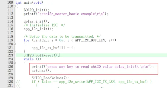
之后我们主函数调用即可,这里通过接收字符进行读取控制,每次接收到一个发送数就读取下我们的数值打印。
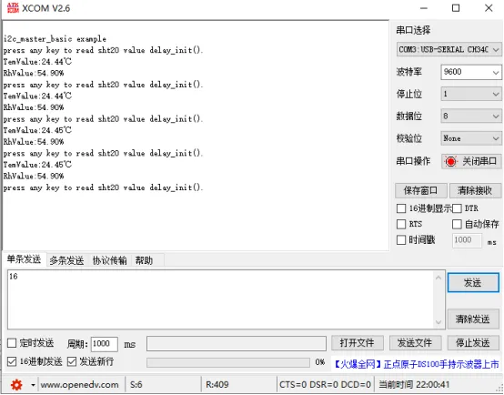
效果如上,可以读取数据的,完全没问题的。
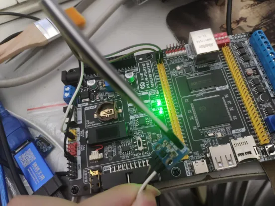
硬件接线图。