STM32测量相位差_stm32 fft 相位
本文使用双ADC同步采样,FFT测量相位差 相位差是相同频率的两个信号的相位之间的差值,如果两个信号频率不同,则谈论相位差没有意义。 采样的数据经过 FFT 之后是一个复数数据,表示了不同频率分量的特征,其模值代表频率分量大小,幅角代表其相位,即 phase=atan2(虚部/实部)。正弦波的相位差就等于基波的相位差。 计算相位差要求使用双通道同步测量两个信号,才能保证采样过程中不产生额外的相位差且采样到的信号保持原始相位。所以不可以使用单 ADC 的双通道采样,单ADC 的双通道采样是两个通道轮流采样,采样时间点不同导致不能保证信号的原始相位。一般可以采用双 ADC 采用同一个触发源,使用两个 DMA 分别传输数据,或者使用同步模式采样。这两个的区别仅仅在于数据的获取方式不同,数据处理方式相同。 1.和普通的 ADC+TIM+DMA 采样相同,只不过是用了两个 ADC,DMA,但是注意触发源要选择同一个 TIM,保证采样的同步性。 2.将 ADC 设置为同步模式,本次选择常规同步模式,这样主 ADC 触发采样后,从ADC也会 同步触发采样。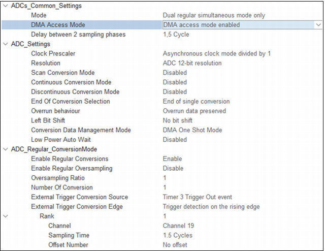 主ADC配置图 通道号,采样时间等可自由设置,采样时间可适当延长,要注意ADC频率和触发频率的关系,ADC采样一次要花费的时钟周期数为ADC位数+采样时间,触发频率不能高于ADC的时钟频率/采样一次花费的周期数,所以采样时间不可过长。 开启两个 ADC 后,在哪个 ADC 的 MODE 中选择同步模式,哪个就是主 ADC,另外一个为从 ADC,在这里只需要配置主 ADC 即可,配置会自动同步到从 ADC,也只需为主 ADC 添加 DMA 即可,DMA 的传输数据宽度要设置成 word,因为在双重模式下,两个 ADC 同一次的采样数据会在 ADC 通用数据寄存器 ADCx_CDR 中作为一个数据存储,然后通过 DMA 传输到内存中,也就是我们设置的承接数据的数组中。其中低 16 位是主 ADC 的采样数据,高 16 位是从 ADC 的采样数据。
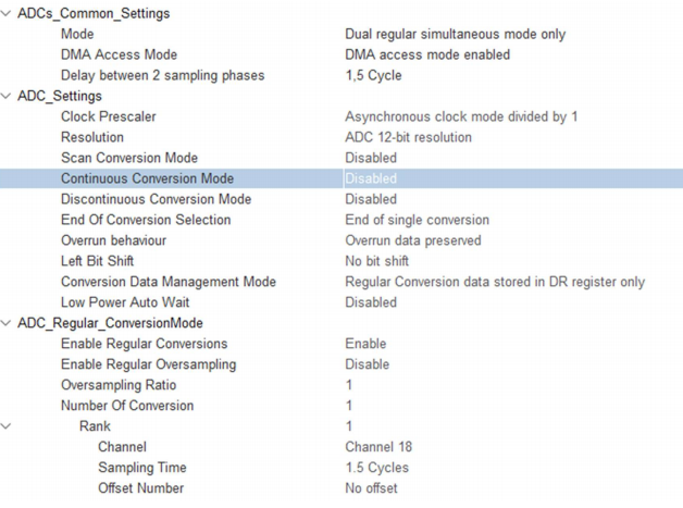
从ADC配置图
代码展示部分
/* USER CODE BEGIN Header *//** ****************************************************************************** * @file : main.c * @brief : Main program body ****************************************************************************** * @attention * * Copyright (c) 2024 STMicroelectronics. * All rights reserved. * * This software is licensed under terms that can be found in the LICENSE file * in the root directory of this software component. * If no LICENSE file comes with this software, it is provided AS-IS. * ****************************************************************************** *//* USER CODE END Header *//* Includes ------------------------------------------------------------------*/#include \"main.h\"#include \"adc.h\"#include \"dma.h\"#include \"memorymap.h\"#include \"tim.h\"#include \"usart.h\"#include \"gpio.h\"/* Private includes ----------------------------------------------------------*//* USER CODE BEGIN Includes */#include \"stdio.h\"#include \"arm_math.h\"#include \"arm_common_tables.h\"#include \"arm_const_structs.h\"/* USER CODE END Includes *//* Private typedef -----------------------------------------------------------*//* USER CODE BEGIN PTD *//* USER CODE END PTD *//* Private define ------------------------------------------------------------*//* USER CODE BEGIN PD */#define length 4096#define phaselength 50//均值滤波需要采集的个数/* USER CODE END PD *//* Private macro -------------------------------------------------------------*//* USER CODE BEGIN PM */float midfliter(float *input,uint32_t inlength);//��ֵ��ƽ��int fputc(int ch,FILE *f){HAL_UART_Transmit(&huart1,(uint8_t *)&ch,1,HAL_MAX_DELAY);return ch;}/* USER CODE END PM *//* Private variables ---------------------------------------------------------*//* USER CODE BEGIN PV */__IO uint8_t adcflag;uint32_t dma_adc_value[length];float adcinput1[length*2];float adcinput2[length*2];uint32_t max_pos;float max_value;uint32_t Freq1;uint32_t Freq2;float phase1;float phase2;float phase[phaselength];float phase_final;uint8_t phasecnt=0;float adcoutput1[length];float adcoutput2[length];float X,Y;/* USER CODE END PV *//* Private function prototypes -----------------------------------------------*/void SystemClock_Config(void);void PeriphCommonClock_Config(void);/* USER CODE BEGIN PFP *//* USER CODE END PFP *//* Private user code ---------------------------------------------------------*//* USER CODE BEGIN 0 *//* USER CODE END 0 *//** * @brief The application entry point. * @retval int */int main(void){ /* USER CODE BEGIN 1 */ /* USER CODE END 1 */ /* MCU Configuration--------------------------------------------------------*/ /* Reset of all peripherals, Initializes the Flash interface and the Systick. */ HAL_Init(); /* USER CODE BEGIN Init */ /* USER CODE END Init */ /* Configure the system clock */ SystemClock_Config(); /* Configure the peripherals common clocks */ PeriphCommonClock_Config(); /* USER CODE BEGIN SysInit */ /* USER CODE END SysInit */ /* Initialize all configured peripherals */ MX_GPIO_Init(); MX_DMA_Init(); MX_ADC1_Init(); MX_TIM3_Init(); MX_USART1_UART_Init(); MX_ADC2_Init(); /* USER CODE BEGIN 2 */HAL_ADC_Start(&hadc2);//开启从ADCHAL_ADCEx_MultiModeStart_DMA(&hadc1,(uint32_t *)dma_adc_value,length);//主ADC开启DMA采集HAL_TIM_Base_Start(&htim3); /* USER CODE END 2 */ /* Infinite loop */ /* USER CODE BEGIN WHILE */ while (1) { /* USER CODE END WHILE */ /* USER CODE BEGIN 3 */HAL_Delay(1);if(adcflag){adcflag=0;HAL_ADC_Stop(&hadc2);for(int i=0;i>16)&0xfff)*3.3f/4095.0f;adcinput2[i*2+1]=0.0f;//printf(\"%.3f,%.3f\\n\\r\",adcinput1[i*2],adcinput2[i*2]);}arm_cfft_f32(&arm_cfft_sR_f32_len4096,adcinput1,0,1);//分别进行FFT变换arm_cfft_f32(&arm_cfft_sR_f32_len4096,adcinput2,0,1);arm_cmplx_mag_f32(adcinput1,adcoutput1,length);arm_cmplx_mag_f32(adcinput2,adcoutput2,length);adcoutput1[0]=0.0f;adcoutput2[0]=0.0f;for(int i=0;i<length;i++){printf(\"%.3f,%.3f\\n\\r\",adcinput1[i*2],adcinput2[i*2]);}//for(int i=0;i(length/2)) max_pos=length-max_pos;Freq1=409600/length*max_pos;X=adcinput1[max_pos*2];Y=adcinput1[max_pos*2+1];phase1=atan2f(Y,X)*180.0f/3.1415926f;//计算波形1的相位arm_max_f32(adcoutput2,length,&max_value,&max_pos);//寻找波形2的频率if(max_pos>(length/2)) max_pos=length-max_pos;Freq2=409600/length*max_pos;X=adcinput2[max_pos*2];Y=adcinput2[max_pos*2+1];phase2=atan2f(Y,X)*180.0f/3.1415926f;//计算波形2的相位phase[phasecnt]=phase1-phase2;//计算相位差if(phase[phasecnt]>180) phase[phasecnt]=phase[phasecnt]-360;//将相位差锁定在-180到+180之内if(phase[phasecnt]=phaselength)//采集50次后进行均值处理{phasecnt=0;phase_final=midfliter(phase,phaselength);}HAL_ADC_Start(&hadc2);HAL_ADCEx_MultiModeStart_DMA(&hadc1,(uint32_t *)dma_adc_value,length*2);} } /* USER CODE END 3 */}/** * @brief System Clock Configuration * @retval None */void SystemClock_Config(void){ RCC_OscInitTypeDef RCC_OscInitStruct = {0}; RCC_ClkInitTypeDef RCC_ClkInitStruct = {0}; /** Supply configuration update enable */ HAL_PWREx_ConfigSupply(PWR_LDO_SUPPLY); /** Configure the main internal regulator output voltage */ __HAL_PWR_VOLTAGESCALING_CONFIG(PWR_REGULATOR_VOLTAGE_SCALE0); while(!__HAL_PWR_GET_FLAG(PWR_FLAG_VOSRDY)) {} /** Initializes the RCC Oscillators according to the specified parameters * in the RCC_OscInitTypeDef structure. */ RCC_OscInitStruct.OscillatorType = RCC_OSCILLATORTYPE_HSE; RCC_OscInitStruct.HSEState = RCC_HSE_ON; RCC_OscInitStruct.PLL.PLLState = RCC_PLL_ON; RCC_OscInitStruct.PLL.PLLSource = RCC_PLLSOURCE_HSE; RCC_OscInitStruct.PLL.PLLM = 5; RCC_OscInitStruct.PLL.PLLN = 192; RCC_OscInitStruct.PLL.PLLP = 2; RCC_OscInitStruct.PLL.PLLQ = 2; RCC_OscInitStruct.PLL.PLLR = 2; RCC_OscInitStruct.PLL.PLLRGE = RCC_PLL1VCIRANGE_2; RCC_OscInitStruct.PLL.PLLVCOSEL = RCC_PLL1VCOWIDE; RCC_OscInitStruct.PLL.PLLFRACN = 0; if (HAL_RCC_OscConfig(&RCC_OscInitStruct) != HAL_OK) { Error_Handler(); } /** Initializes the CPU, AHB and APB buses clocks */ RCC_ClkInitStruct.ClockType = RCC_CLOCKTYPE_HCLK|RCC_CLOCKTYPE_SYSCLK |RCC_CLOCKTYPE_PCLK1|RCC_CLOCKTYPE_PCLK2 |RCC_CLOCKTYPE_D3PCLK1|RCC_CLOCKTYPE_D1PCLK1; RCC_ClkInitStruct.SYSCLKSource = RCC_SYSCLKSOURCE_PLLCLK; RCC_ClkInitStruct.SYSCLKDivider = RCC_SYSCLK_DIV1; RCC_ClkInitStruct.AHBCLKDivider = RCC_HCLK_DIV2; RCC_ClkInitStruct.APB3CLKDivider = RCC_APB3_DIV2; RCC_ClkInitStruct.APB1CLKDivider = RCC_APB1_DIV2; RCC_ClkInitStruct.APB2CLKDivider = RCC_APB2_DIV2; RCC_ClkInitStruct.APB4CLKDivider = RCC_APB4_DIV2; if (HAL_RCC_ClockConfig(&RCC_ClkInitStruct, FLASH_LATENCY_4) != HAL_OK) { Error_Handler(); }}/** * @brief Peripherals Common Clock Configuration * @retval None */void PeriphCommonClock_Config(void){ RCC_PeriphCLKInitTypeDef PeriphClkInitStruct = {0}; /** Initializes the peripherals clock */ PeriphClkInitStruct.PeriphClockSelection = RCC_PERIPHCLK_ADC; PeriphClkInitStruct.PLL2.PLL2M = 2; PeriphClkInitStruct.PLL2.PLL2N = 16; PeriphClkInitStruct.PLL2.PLL2P = 2; PeriphClkInitStruct.PLL2.PLL2Q = 2; PeriphClkInitStruct.PLL2.PLL2R = 2; PeriphClkInitStruct.PLL2.PLL2RGE = RCC_PLL2VCIRANGE_3; PeriphClkInitStruct.PLL2.PLL2VCOSEL = RCC_PLL2VCOWIDE; PeriphClkInitStruct.PLL2.PLL2FRACN = 0; PeriphClkInitStruct.AdcClockSelection = RCC_ADCCLKSOURCE_PLL2; if (HAL_RCCEx_PeriphCLKConfig(&PeriphClkInitStruct) != HAL_OK) { Error_Handler(); }}/* USER CODE BEGIN 4 */float midfliter(float *input,uint32_t inlength){arm_sort_instance_f32 *S;float output[inlength];arm_sort_init_f32(S,(arm_sort_alg)4,(arm_sort_dir)1);arm_sort_f32(S,input,output,inlength);return (output[23]+output[24]+output[25]+output[26])/4.0f;}void HAL_ADC_ConvCpltCallback(ADC_HandleTypeDef *hadc){adcflag=1;}/* USER CODE END 4 *//** * @brief This function is executed in case of error occurrence. * @retval None */void Error_Handler(void){ /* USER CODE BEGIN Error_Handler_Debug */ /* User can add his own implementation to report the HAL error return state */ __disable_irq(); while (1) { } /* USER CODE END Error_Handler_Debug */}#ifdef USE_FULL_ASSERT/** * @brief Reports the name of the source file and the source line number * where the assert_param error has occurred. * @param file: pointer to the source file name * @param line: assert_param error line source number * @retval None */void assert_failed(uint8_t *file, uint32_t line){ /* USER CODE BEGIN 6 */ /* User can add his own implementation to report the file name and line number, ex: printf(\"Wrong parameters value: file %s on line %d\\r\\n\", file, line) */ /* USER CODE END 6 */}#endif /* USE_FULL_ASSERT */

