网络基础15-16:MSTP +VRRP综合实验
MSTP 、VRRP综合实验,MSTP涵盖根桥选举、边缘端口、BPDU 保护、根保护、TC 保护 等功能验证。
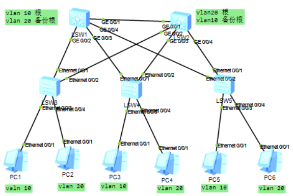
一、实验拓扑与设备规划
- 核心层:LSW1(VLAN10 根桥、VLAN20 备份根)、LSW2(VLAN20 根桥、VLAN10 备份根)。
- 接入层:LSW3(连 PC1、PC2)、LSW4(连 PC3、PC4)、LSW5(连 PC5、PC6)。
- 测试设备:LSW6(测试 BPDU 保护)、LSW7(测试根保护)、LSW5开启TC保护。
二、基础网络配置(VLAN、接口模式)
1. 核心交换机(LSW1、LSW2)
# LSW1配置 (LSW2的优先级改变)system-viewvlan batch 10 20port-group group-member GigabitEthernet 0/0/1 to GigabitEthernet 0/0/4 #简写p g g0/0/1 to g0/0/4port link-type trunkport trunk allow-pass vlan all2. 接入交换机(LSW3、LSW4、LSW5)
# LSW3配置(连PC1、PC2;PC1→VLAN10,PC2→VLAN20)system-viewvlan batch 10 20interface Ethernet 0/0/3 port link-type accessport default vlan 10interface Ethernet 0/0/4port link-type accessport default vlan 10quitport-group group-member Ethernet 0/0/1 Ethernet 0/0/2 #简写p g e0/0/1 e0/0/2port link-type trunkport trunk allow-pass vlan all三、MSTP 核心配置(多实例与根桥选举)
1. 核心交换机(LSW1、LSW2)
# LSW1:Instance10(VLAN10)根桥,Instance20(VLAN20)备份根stp enablestp mode mstpstp region-configuration region-name A # 区域名统一为A region-level 2 # 区域级别2 instance 10 vlan 10 # 实例10映射VLAN10 instance 20 vlan 20 # 实例20映射VLAN20 active region-configuration # 激活配置quitstp instance 10 priority 4096 # 实例10优先级(最小,成为根)stp instance 20 priority 8192 # 实例20优先级(大于LSW2的4096,成为备份)stp instance 0 priority 4096 # 实例0(默认)优先级,成为根# LSW2:Instance20(VLAN20)根桥,Instance10(VLAN10)备份根stp enablestp mode mstpstp region-configuration region-name A region-level 2 instance 10 vlan 10 instance 20 vlan 20 active region-configurationquitstp instance 10 priority 8192 # 实例10备份根stp instance 20 priority 4096 # 实例20根桥stp instance 0 priority 8192 # 实例0备份根2. 接入交换机(LSW3、LSW4、LSW5)
stp enablestp mode mstpstp region-configuration region-name A region-level 2 instance 10 vlan 10 instance 20 vlan 20 active region-configurationquit# 实例优先级默认,由核心自动选举根桥验证 1:根桥与链路状态
- 在 LSW3 上执行:display stp brief
MSTID Port Role STP State Protection 0 Ethernet0/0/1 ROOT FORWARDING NONE # 确认Instance0根桥为LSW1 0 Ethernet0/0/2 ALTE DISCARDING NONE 0 Ethernet0/0/3 DESI FORWARDING BPDU 0 Ethernet0/0/4 DESI FORWARDING BPDU 10 Ethernet0/0/1 ROOT FORWARDING NONE # 确认Instance10根桥为LSW 10 Ethernet0/0/2 ALTE DISCARDING NONE 10 Ethernet0/0/3 DESI FORWARDING BPDU 20 Ethernet0/0/1 ALTE DISCARDING NONE 20 Ethernet0/0/2 ROOT FORWARDING NONE # 确认Instance10根桥为LSW 20 Ethernet0/0/4 DESI FORWARDING BPDU
- 观察核心间链路(如 GE0/0/1、GE0/0/4)在不同实例中 阻塞 / 转发,实现负载均衡。
四、边缘端口与 BPDU 保护(LSW3)
配置
# LSW3:将PC连接端口标记为边缘端口,启用BPDU保护port-group group-member Ethernet 0/0/3 Ethernet 0/0/4 # 假设这两个端口连PC stp edged-port enable # 边缘端口:跳过STP协商,直接转发quitstp bpdu-protection # 启用BPDU保护:边缘端口收BPDU则关闭验证 2:边缘端口行为
-
正常状态:
[Huawei]display stp brief MSTID Port Role STP State Protection 0 Ethernet0/0/1 ROOT FORWARDING NONE 0 Ethernet0/0/2 ALTE DISCARDING NONE 0 Ethernet0/0/3 DESI FORWARDING BPDU 0 Ethernet0/0/4 DESI FORWARDING BPDU 10 Ethernet0/0/1 ROOT FORWARDING NONE 10 Ethernet0/0/2 ALTE DISCARDING NONE 10 Ethernet0/0/3 DESI FORWARDING BPDU #e0/0/3为指定端口 20 Ethernet0/0/1 ALTE DISCARDING NONE 20 Ethernet0/0/2 ROOT FORWARDING NONE 20 Ethernet0/0/4 DESI FORWARDING BPDU #e0/0/4为指定端口 -
模拟攻击:LSW6 连 LSW3 的 E0/0/3
连接后,LSW3 的 E0/0/3 因收 BPDU 触发保护:Ethernet0/0/3 接口消失了(关闭了)
[Huawei]display stp brief MSTID Port Role STP State Protection 0 Ethernet0/0/1 ROOT FORWARDING NONE 0 Ethernet0/0/2 ALTE DISCARDING NONE 0 Ethernet0/0/4 DESI FORWARDING BPDU 10 Ethernet0/0/1 ROOT FORWARDING NONE 10 Ethernet0/0/2 ALTE DISCARDING NONE 20 Ethernet0/0/1 ALTE DISCARDING NONE 20 Ethernet0/0/2 ROOT FORWARDING NONE 20 Ethernet0/0/4 DESI FORWARDING BPDU恢复:
interface Ethernet 0/0/3 undo stp bpdu-protection 五、根保护(LSW4 的 E0/0/3 接口,连 LSW7)
# LSW4:对连接下游的端口启用根保护interface Ethernet 0/0/3 stp root-protection # 防止下游设备抢占根桥quit# LSW7:模拟恶意根桥(优先级更低,试图抢占)system-viewstp enablestp mode mstpstp instance 10 priority 0 # 优先级0(比LSW1的4096小)验证 3:根保护生效
连接 LSW7 与 LSW4 的 E0/0/3 后,在 LSW4 上执行:
display stp brief MSTID Port Role STP State Protection 0 Ethernet0/0/1 ROOT FORWARDING NONE 0 Ethernet0/0/2 ALTE DISCARDING NONE 0 Ethernet0/0/3 DESI DISCARDING ROOT 0 Ethernet0/0/4 DESI FORWARDING NONE 10 Ethernet0/0/1 ROOT FORWARDING NONE # 根桥仍为LSW1(未被抢占) 10 Ethernet0/0/2 ALTE DISCARDING NONE 10 Ethernet0/0/3 DESI DISCARDING ROOT # Ethernet0/0/3状态变为DISCARDING(拒绝更优BPDU) 20 Ethernet0/0/1 ALTE DISCARDING NONE 20 Ethernet0/0/2 ROOT FORWARDING NONE 20 Ethernet0/0/4 DESI FORWARDING NONE恢复:移除 LSW7,E0/0/3 自动恢复 FORWARDING。
六、TC 保护(LSW5)
配置
# LSW5:限制TC报文频率,防止MAC表频繁刷新stp tc-protection threshold 5 # TC报文阈值设为5,超过后抑制验证 4:TC 保护
- 模拟攻击:通过工具(或频繁插拔链路)向 LSW5 发送大量 TC BPDU。
- 查看状态:
display stp tc-protection # 查看阈值配置display stp statistics # 观察TC报文计数,超过5后触发抑制 - 攻击停止后,TC 计数回落,保护自动解除。
七、VRRP 配置
1.、VRRP 设计逻辑
- VLAN10:LSW1 作为 MSTP 根桥,同时担任 VRRP 主网关(优先级 110),LSW2 为备用。
- VLAN20:LSW2 作为 MSTP 根桥,同时担任 VRRP 主网关(优先级 110),LSW1 为备用。
- 虚拟 IP:
192.168.10.1(VLAN10)、192.168.20.1(VLAN20),与主机网关一致。
2.、LSW1(核心交换机 1)配置
system-viewsysname LSW1# ========== 先完成MSTP配置(参考之前“三”) ========== ## ---------- VLAN10 三层接口(主网关) ---------- #interface Vlanif10 ip address 192.168.10.4 255.255.255.0 # 物理IP(唯一,与LSW2的192.168.10.5区分) vrrp vrid 10 virtual-ip 192.168.10.1 # 虚拟IP,主机默认网关 vrrp vrid 10 priority 110 # 优先级高于备用(默认100),成为主网关 vrrp vrid 10 preempt-mode # 默认开启抢占,恢复后夺回主角色quit# ---------- VLAN20 三层接口(备网关) ---------- #interface Vlanif20 ip address 192.168.20.4 255.255.255.0 # 物理IP vrrp vrid 20 virtual-ip 192.168.20.1 # 虚拟IP # 优先级默认100,LSW2的VLAN20优先级110,故此处为备用quit3、LSW2(核心交换机 2)配置
system-viewsysname LSW2# ========== 先完成MSTP配置(参考之前“三”) ========== ## ---------- VLAN10 三层接口(备网关) ---------- #interface Vlanif10 ip address 192.168.10.5 255.255.255.0 # 物理IP vrrp vrid 10 virtual-ip 192.168.10.1 # 与LSW1一致的虚拟IP # 优先级默认100,LSW1的VLAN10优先级110,故此处为备用quit# ---------- VLAN20 三层接口(主网关) ---------- #interface Vlanif20 ip address 192.168.20.5 255.255.255.0 # 物理IP vrrp vrid 20 virtual-ip 192.168.20.1 # 虚拟IP vrrp vrid 20 priority 110 # 优先级高于备用(LSW1的100),成为主网关 vrrp vrid 20 preempt-mode # 开启抢占quit4、关键验证步骤
(1)查看 VRRP 状态
-
LSW1 上:
# Vlanif10 → VRID 10 → Master(优先级110)# Vlanif20 → VRID 20 → Backup(优先级100)[Huawei-Vlanif10]display vrrp briefVRID State Interface Type Virtual IP ----------------------------------------------------------------10 Master Vlanif10 Normal 192.168.10.1 20 Backup Vlanif20 Normal 192.168.20.1 ----------------------------------------------------------------Total:2 Master:1 Backup:1 Non-active:0 -
LSW2 上:
# Vlanif10 → VRID 10 → Backup(优先级100)# Vlanif20 → VRID 20 → Master(优先级110)[Huawei]dis vrrp briefVRID State Interface Type Virtual IP ----------------------------------------------------------------10 Backup Vlanif10 Normal 192.168.10.1 20 Master Vlanif20 Normal 192.168.20.1 ----------------------------------------------------------------Total:2 Master:1 Backup:1 Non-active:0
(2)故障切换测试
-
模拟 LSW1 故障(断开 g0/0/1接口):
LSW1: int vlan 10[Huawei-Vlanif10]vrrp vrid 10 track interface g0/0/1 reduced 11 #track interface 多接口跟踪, reduced 11 断开优先级减11[Huawei-Vlanif10]quit[Huawei]int g0/0/1[Huawei-GigabitEthernet0/0/1]shutdown
- 验证
LSW1: display vrrp briefVRID State Interface Type Virtual IP ----------------------------------------------------------------10 Backup Vlanif10 Normal 192.168.10.1 20 Backup Vlanif20 Normal 192.168.20.1 ----------------------------------------------------------------Total:2 Master:0 Backup:2 Non-active:0 LSW2: display vrrp briefVRID State Interface Type Virtual IP ----------------------------------------------------------------10 Master Vlanif10 Normal 192.168.10.1 20 Master Vlanif20 Normal 192.168.20.1 ----------------------------------------------------------------Total:2 Master:2 Backup:0 Non-active:0 reduced 值的选择:需确保 优先级 - reduced 后 低于 Backup 设备,否则无法触发切换。在 LSW2 上观察:Vlanif10 的 VRRP 状态切换为 Master,PC1(VLAN10)仍可 ping 通 192.168.10.1。
抢占模式:若不希望频繁抢占(如避免流量瞬断),可配置 vrrp vrid 10 preempt-mode timer delay 5(延迟 5 秒抢占)。
-
恢复 LSW1:
LSW1: interface Vlanif10 undo shutdownLSW1 的 Vlanif10 因 抢占模式 重新成为 Master,业务无中断。
(3)联动 MSTP 验证
- 断开 LSW1 与 LSW2 的物理链路(如 GE0/0/1),MSTP 会重新计算拓扑,阻塞备用链路;
- 同时 VRRP 会根据 接口状态 或 BFD 联动(若配置)快速切换,确保网关冗余与二层拓扑一致。
5、扩展优化(可选)
(1)BFD 与 VRRP 联动
为加速故障检测(默认 VRRP 心跳 2 秒,可通过 BFD 压缩到毫秒级):
# LSW1 Vlanif10示例:interface Vlanif10 vrrp vrid 10 bfd enable # 启用BFD联动 vrrp vrid 10 bfd session-name lsw1-lsw2 # BFD会话名quit# LSW2 对称配置,实现双向检测(2) _track 接口状态
监控物理链路状态,链路故障时自动降低 VRRP 优先级:
# LSW1 Vlanif10:若GE0/0/2(连LSW3)故障,VRRP优先级降为90interface Vlanif10 vrrp vrid 10 track interface GigabitEthernet 0/0/2 reduced 20 # 优先级减20quit核心价值
- MSTP+VRRP 联动:二层根桥与三层网关角色对齐,减少跨设备转发,提升效率。
- 双活冗余:VLAN10 和 VLAN20 的主网关分别由 LSW1、LSW2 承担,实现负载均衡。
- 快速收敛:通过 BFD 或 Track 机制,故障切换时间压缩至百毫秒级,保障业务连续性。
以上配置完整覆盖 二层冗余(MSTP)+ 三层冗余(VRRP),适配园区网核心层高可用设计。
关键命令速查
stp region-configurationinstance 10 vlan 10stp instance 10 priority 4096stp edged-port enablestp bpdu-protectionstp root-protection(接口下)stp tc-protection threshold 5display stp brief、display stp instance X brief