无人机开发分享——机载ROS2系统通过DDS实现对开源飞控PX4在线规划与控制_px4 ros2
在无人机的机载智能系统的开发中,由于ROS2系统相较于ROS1的分布式通讯等优点,现在机载开发也已逐渐由ROS1逐渐过渡到ROS2系统开发上来。本文的开发分享主要分享如何在机载ROS2系统上开发机载程序对开源飞控PX4实现规划与控制。
STEP1 ROS2与PX4通讯
以前做过无人机机载开发的都知道,ROS1与px4使用了mavros与mavlink进行通讯,机载端将mavlink消息与mavros消息进行实时转换。到了ROS2,这一通讯体质已进行了改变(mavros仍然可用,但不是主流),ROS2采用XRCE-DDS模块进行通讯。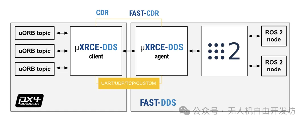
PX4端内部使用UORB进行通讯,对外采用uXRCE-DDS的客户端进行消息转换对外发布(串口、网口),ROS2平台运行uXRCE-DDS代理端(服务端)将收到的信息转换为ROS2的topic/service进行发布。
STEP2 ROS2开发软件对PX4进行规划控制
本部分可以通过硬件在环仿真的形式完成,即PX4硬件飞控、机载3588/nvidia板硬件、gazebo软件(之前的文章有介绍过如何仿真)。
首先设置PX4飞控为HITL硬件在环仿真模式,在机载板安装ROS2系统,XRCE-dds的客户端在PX4软件自动运行,仅需在ROS2端下载代理端即可。
git clone -b v2.4.2 https://github.com/eProsima/Micro-XRCE-DDS-Agent.gitcd Micro-XRCE-DDS-Agentmkdir buildcd buildcmake ..makesudo make installsudo ldconfig /usr/local/lib/MicroXRCEAgent udp4 -p 8888开启udp本地网口通讯,进行uorb消息与ros2消息的转换。
搞定试验基础后,我们可以先实现一个基础控制,起飞悬停操作。
首先,我们需要下载一个px4适配ROS2的msg包,里面是通用的PX4控制消息包。
git clone https://github.com/PX4/px4_msgs.git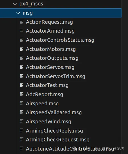
然后在ROS2程序中建立一个PX4-ROS2的控制功能包
class OffboardControl : public rclcpp::Node{public:OffboardControl() : Node(\"offboard_control\"){offboard_control_mode_publisher_ = this->create_publisher<OffboardControlMode>(\"fmu/in/offboard_control_mode\", 10);trajectory_setpoint_publisher_ = this->create_publisher<TrajectorySetpoint>(\"fmu/in/trajectory_setpoint\", 10);vehicle_command_publisher_ = this->create_publisher<VehicleCommand>(\"fmu/in/vehicle_command\", 10);offboard_setpoint_counter_ = 0;auto timer_callback = [this]() -> void {if (offboard_setpoint_counter_ == 10) {// Change to Offboard mode after 10 setpointsthis->publish_vehicle_command(VehicleCommand::VEHICLE_CMD_DO_SET_MODE, 1, 6);// Arm the vehiclethis->arm();}// offboard_control_mode needs to be paired with trajectory_setpointpublish_offboard_control_mode();publish_trajectory_setpoint();// stop the counter after reaching 11if (offboard_setpoint_counter_ < 11) {offboard_setpoint_counter_++;}};timer_ = this->create_wall_timer(100ms, timer_callback);}void arm();void disarm();private:rclcpp::TimerBase::SharedPtr timer_;rclcpp::Publisher<OffboardControlMode>::SharedPtr offboard_control_mode_publisher_;rclcpp::Publisher<TrajectorySetpoint>::SharedPtr trajectory_setpoint_publisher_;rclcpp::Publisher<VehicleCommand>::SharedPtr vehicle_command_publisher_;std::atomic<uint64_t> timestamp_; //!< common synced timestampeduint64_t offboard_setpoint_counter_; //!< counter for the number of setpoints sentvoid publish_offboard_control_mode();void publish_trajectory_setpoint();void publish_vehicle_command(uint16_t command, float param1 = 0.0, float param2 = 0.0);};先建立一个继承于rclcpp node的控制类,建立三个话题发布,offboard_control_mode_publisher_,trajectory_setpoint_publisher_,vehicle_command_publisher_分别为设置offboard模式的,轨迹跟踪目标点,无人机控制指令的消息。
然后声明一个lamda(大家有兴趣可以搜索学习下)回调函数timer_callback,里面实现对消息内容的填充与发布。
/** * @brief Send a command to Arm the vehicle */void OffboardControl::arm(){publish_vehicle_command(VehicleCommand::VEHICLE_CMD_COMPONENT_ARM_DISARM, 1.0);RCLCPP_INFO(this->get_logger(), \"Arm command send\");}/** * @brief Send a command to Disarm the vehicle */void OffboardControl::disarm(){publish_vehicle_command(VehicleCommand::VEHICLE_CMD_COMPONENT_ARM_DISARM, 0.0);RCLCPP_INFO(this->get_logger(), \"Disarm command send\");}/** * @brief Publish the offboard control mode. * For this example, only position and altitude controls are active. */void OffboardControl::publish_offboard_control_mode(){OffboardControlMode msg{};msg.position = true;msg.velocity = false;msg.acceleration = false;msg.attitude = false;msg.body_rate = false;msg.timestamp = this->get_clock()->now().nanoseconds() / 1000;offboard_control_mode_publisher_->publish(msg);}/** * @brief Publish a trajectory setpoint * For this example, it sends a trajectory setpoint to make the * vehicle hover at 5 meters with a yaw angle of 180 degrees. */void OffboardControl::publish_trajectory_setpoint(){TrajectorySetpoint msg{};msg.position = {0.0, 0.0, -5.0};msg.yaw = -3.14; // [-PI:PI]msg.timestamp = this->get_clock()->now().nanoseconds() / 1000;trajectory_setpoint_publisher_->publish(msg);}/** * @brief Publish vehicle commands * @param command Command code (matches VehicleCommand and MAVLink MAV_CMD codes) * @param param1 Command parameter 1 * @param param2 Command parameter 2 */void OffboardControl::publish_vehicle_command(uint16_t command, float param1, float param2){VehicleCommand msg{};msg.param1 = param1;msg.param2 = param2;msg.command = command;msg.target_system = 0;msg.target_component = 1;msg.source_system = 1;msg.source_component = 1;msg.from_external = true;msg.timestamp = this->get_clock()->now().nanoseconds() / 1000;vehicle_command_publisher_->publish(msg);}以解锁为例,会调用publish_vehicle_command函数,将解锁指令填充到控制指令里,然后publish_vehicle_command该函数会对VehicleComman的msg消息进行数据填充,然后发布vehicle_command_publisher_->publish(msg)。发布offboard模式转换和轨迹跟踪点同理。
最后建立main函数,生成节点对象并运行
int main(int argc, char *argv[]){std::cout << \"Starting offboard control node...\" << std::endl;setvbuf(stdout, NULL, _IONBF, BUFSIZ);rclcpp::init(argc, argv);rclcpp::spin(std::make_shared<OffboardControl>());rclcpp::shutdown();return 0;}对这段ros2的功能包进行编译后,ROS2终端启动下该功能包节点即可。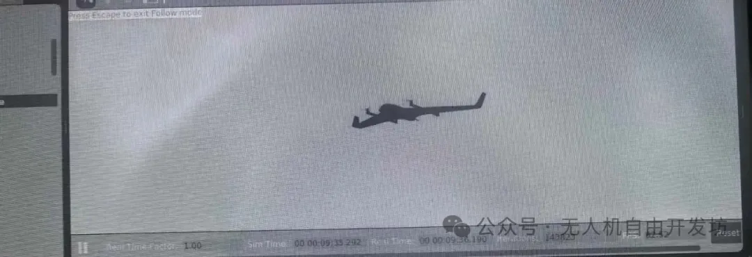
STEP3 机载自定义更多管理规划软件
在实现基础控制后,可以在机载端自己设置管理软件,如通过区域设计侦察航线发送到轨迹跟踪点,通过状态机设计何时解锁、起飞、RTL,根据具体需求,如区域遍历,实现机载的智能控制。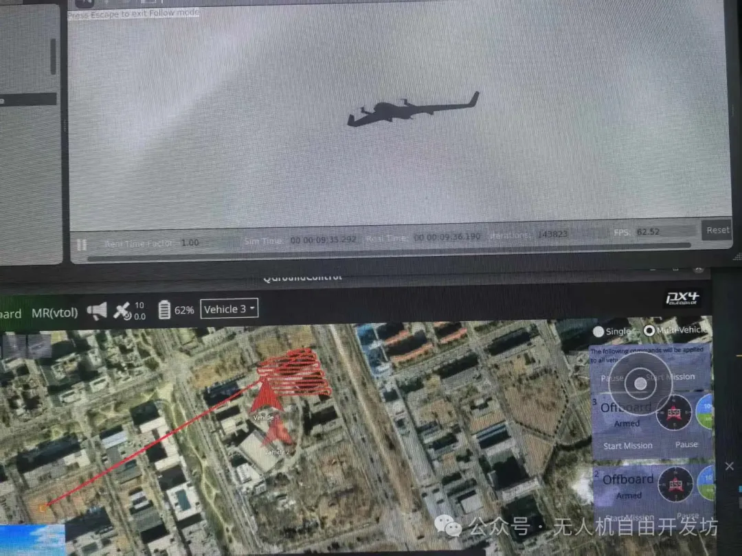
智能化是未来无人机发展的重要方向,因此无人机的机载智能软件的开发十分重要,大家可以着手对该方向进行研究,同时可以共同沟通分享开发经验。
后期的开发经验将会继续分享,文章转自我的公众号(无人机自由开发坊),或者加入我的开发群共同讨论开发经验。过期可添加UavFree95


