【3D手眼标定案例】--SCARA机器人手眼标定系统详解
* This example explains how to perform the hand-eye calibration for* a SCARA robot. In this case, the camera is attached to the robot tool* and the calibration object is stationary with respect to the robot.* * Provide the description file of the calibration plate and the* camera parameters of the previously calibrated cameraCalibObjDescr := \'calibrate_hand_eye_scara_setup_01_calplate.cpd\'gen_cam_par_area_scan_division (0.004938, -10379.136, 4.65138e-006, 4.65e-006, 617.294, 534.687, 1280, 1024, CameraParam)* dev_close_window ()dev_open_window_fit_size (0, 0, 1280, 1024, 640, -1, WindowHandle)set_display_font (WindowHandle, 14, \'mono\', \'true\', \'false\')dev_update_off ()* * 1. Acquire calibration images and corresponding robot poses* * Create a new calibration modelcreate_calib_data (\'hand_eye_scara_moving_cam\', 1, 1, CalibDataID)* Set the camera parameters in the calibration modelset_calib_data_cam_param (CalibDataID, 0, [], CameraParam)* Set the calibration plate in the calibration modelset_calib_data_calib_object (CalibDataID, 0, CalibObjDescr)for Index := 1 to 10 by 1 * Read the calibration image read_image (CalibImage, \'3d_machine_vision/hand_eye/scara_moving_cam_setup_01_calib_\' + Index$\'02\') * Read the corresponding robot pose (pose of the tool in the * robot base coordinate system) read_pose (\'scara_moving_cam_setup_01_tool_in_base_pose_\' + Index$\'02\' + \'.dat\', ToolInBasePose) * Set the robot pose in the calibration model set_calib_data (CalibDataID, \'tool\', Index, \'tool_in_base_pose\', ToolInBasePose) * Determine the pose of the calibration plate in the camera * coordinate system and set the pose in the calibration model find_calib_object (CalibImage, CalibDataID, 0, 0, Index, [], []) * Visualize dev_display (CalibImage) get_calib_data_observ_pose (CalibDataID, 0, 0, Index, ObjInCameraPose) disp_caltab (WindowHandle, CalibObjDescr, CameraParam, ObjInCameraPose, 1) disp_message (WindowHandle, \'Calibration image \' + Index + \' of 10\', \'window\', 12, 12, \'black\', \'true\') wait_seconds (0.2)endfordisp_continue_message (WindowHandle, \'black\', \'true\')stop ()* * 2. Check the input poses for consistency* check_hand_eye_calibration_input_poses (CalibDataID, 0.05, 0.005, Warnings)if (|Warnings| != 0) * There were problem detected in the input poses. Inspect Warnings and * remove erroneous poses with remove_calib_data and remove_calib_data_observ. dev_inspect_ctrl (Warnings) stop ()endif* * 3. Perform the hand-eye calibration* calibrate_hand_eye (CalibDataID, Errors)* Get the result of the calibration, i.e., the pose of* the robot base in the camera coordinate systemget_calib_data (CalibDataID, \'camera\', 0, \'tool_in_cam_pose\', ToolInCamPosePre)* Free the calibration modelclear_calib_data (CalibDataID)* Visualizedisp_preliminary_result (WindowHandle, ToolInCamPosePre, Errors)disp_continue_message (WindowHandle, \'black\', \'true\')stop ()* * 3. Fix the pose ambiguity* * When calibrating a SCARA robot, it is impossible to determine* all pose parameters unambiguously. In case of a moving* camera, the Z translation of ObjInBasePose cannot be determined.* Therefore, it is necessary to fix the unknown translation in* Z by moving the robot to a pose of known height in the camera* coordinate system. Because normally the camera does not see* the object if the tool is moved to the object, the robot is* moved to two poses. For this, the calibration plate is placed* at an arbitrary position. The robot is then manually moved such* that the camera can observe the calibration plate. Now, an image* of the calibration plate is acquired and the robot pose is* queried (-> ToolInBasePoseRef1). From the image, the pose of the* calibration plate in the camera coordinate system can be* determined (-> ObjInCamPoseRef1). Afterwards, the tool of the* robot is manually moved to the origin of the calibration plate* (-> ToolInBasePoseRef2). These three poses and the result of the* calibration (ToolInCamPosePre) can be used to fix the* Z ambiguity by using the procedure fix_scara_ambiguity_moving_cam:read_image (ImageRef1, \'3d_machine_vision/hand_eye/scara_moving_cam_setup_01_calib_ref_1\')get_calib_plate_pose (ImageRef1, CameraParam, CalibObjDescr, ObjInCamPoseRef1)read_pose (\'scara_moving_cam_setup_01_tool_in_base_pose_ref_1.dat\', ToolInBasePoseRef1)read_pose (\'scara_moving_cam_setup_01_tool_in_base_pose_ref_2.dat\', ToolInBasePoseRef2)fix_scara_ambiguity_moving_cam (ToolInCamPosePre, ObjInCamPoseRef1, ToolInBasePoseRef1, ToolInBasePoseRef2, ZCorrection)set_origin_pose (ToolInCamPosePre, 0, 0, ZCorrection, ToolInCamPose)* * Visualizedisp_final_results (WindowHandle, ToolInCamPosePre, ToolInCamPose)disp_end_of_program_message (WindowHandle, \'black\', \'true\')* * After the hand-eye calibration is performed, the resulting pose* ToolInCamPose can be used in robotic grasping applications:* Let us assume that the camera acquires an image of the object that* should be grasped. This image was taken at a certain robot pose* (-> ToolInBasePose). From the image, the pose of the object in the* camera coordinate system must be determined (-> ObjInCamPose) by* using image processing.* Based on these two poses and the result of the calibration* (ToolInCamPose), the robot pose can be computed that is necessary* to grasp the object (-> ObjInBasePose):pose_invert (ToolInCamPose, CamInToolPose)create_pose (-0.0043, 0.0085, 0.087, 0.445, 0.068, 355.9, \'Rp+T\', \'gba\', \'point\', ObjInCamPose)create_pose (0.2612, 0.084, 0.1731, 0, 0, 178.128, \'Rp+T\', \'gba\', \'point\', ToolInBasePose)pose_compose (CamInToolPose, ObjInCamPose, ObjInToolPose)pose_compose (ToolInBasePose, ObjInToolPose, ObjInBasePose)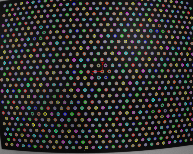
SCARA机器人手眼校准系统深度解析
1. 代码功能详细解析
1.1 系统初始化
- 初始化参数:设置标定板描述文件和相机参数
- 创建显示窗口:适配图像尺寸且关闭自动更新
- 关键操作:
gen_cam_par_area_scan_division: 生成面阵相机参数(像素大小、焦距、畸变参数等)create_calib_data: 创建SCARA专用移动相机手眼校准数据结构
1.2 数据采集
- 循环采集10组校准数据:
- 读取校准图像
- 获取当前机器人工具在基座坐标系中的位姿 (
ToolInBasePose) - 在图像中定位标定板,计算标定板在相机坐标系中的位姿 (
ObjInCameraPose) - 可视化显示标定板位置
1.3 数据验证
check_hand_eye_calibration_input_poses: 验证输入的机器人位姿是否合理(旋转角度差异>0.05rad,平移>5mm)- 检查警告信息并移除异常位姿点
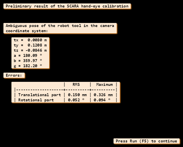
1.4 初步校准
calibrate_hand_eye: 执行手眼校准计算get_calib_data: 获取初步校准结果 - 工具在相机坐标系中的位姿 (ToolInCamPosePre)
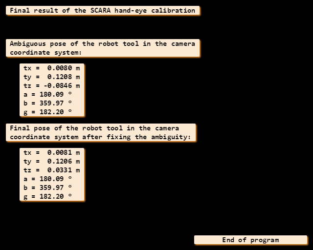
1.5 解决SCARA特殊歧义问题
- 读取两个参考位姿:
- 机器人观察到标定板的位姿 (
ToolInBasePoseRef1) - 机器人末端精确对标定板原点的位姿 (
ToolInBasePoseRef2)
- 机器人观察到标定板的位姿 (
get_calib_plate_pose: 从图像中提取标定板位姿 (ObjInCamPoseRef1)fix_scara_ambiguity_moving_cam: 计算Z轴歧义修正值set_origin_pose: 应用Z轴修正获取最终校准结果 (ToolInCamPose)
1.6 应用示例
- 位姿转换计算抓取位置:
- 计算相机在工具坐标系中的位姿 (
CamInToolPose) - 组合位姿计算物体在工具坐标系中的位置 (
ObjInToolPose) - 组合位姿计算物体在基座坐标系中的位置 (
ObjInBasePose)
- 计算相机在工具坐标系中的位姿 (
2. 功能应用场景
该代码适用于以下SCARA机器人典型应用:
-
精密电子装配
- PCB板元件插装
- 芯片贴装校准
- SMT设备拾取系统
-
小型零件分拣
- 手表零件装配
- 医疗器械组装
- 微型机械组装
-
快速抓取系统
- 传送链零件拾取
- 高速分拣系统
- 自动插装设备
-
实验室自动化
- 微孔板操作
- 样本分选系统
- 细胞培养设备
3. 完整步骤流程及流程图

4. 关键函数算子解析
find_calib_object (CalibImage, CalibDataID, 0, 0, Index, [], [])
- 功能:在图像中识别标定板并计算位姿
- 参数:
CalibImage:输入图像CalibDataID:校准数据结构ID0, 0:相机和标定对象索引Index:当前位姿索引[], []:保留参数
- 内部算法:基于边缘检测和特征匹配
fix_scara_ambiguity_moving_cam (ToolInCamPosePre, ObjInCamPoseRef1, ToolInBasePoseRef1, ToolInBasePoseRef2, ZCorrection)
- 功能:解决SCARA机器人Z轴方向位姿歧义
- 参数:
ToolInCamPosePre:初步校准结果ObjInCamPoseRef1:参考位姿1中标定板在相机坐标系的位姿ToolInBasePoseRef1:参考位姿1的机器人位姿ToolInBasePoseRef2:参考位姿2的机器人位姿ZCorrection:返回的Z轴校正值
- 数学原理:
ΔZ = [T2(z) - T1(z)] - (R1-1 * R2 * O1)(z) + O1(z)其中T是平移向量,R是旋转矩阵,O是标定板位置
set_origin_pose (ToolInCamPosePre, 0, 0, ZCorrection, ToolInCamPose)
- 功能:应用Z轴校正
- 参数:
ToolInCamPosePre:原始位姿0, 0:X/Y轴校正值(保持为0)ZCorrection:Z轴校正值ToolInCamPose:输出校正后位姿
get_calib_plate_pose (Image, CameraParam, CalibObjDescr, ObjInCamPose)
- 功能:从单张图像计算标定板位姿
- 参数:
Image:输入图像CameraParam:相机内部参数CalibObjDescr:标定板描述文件ObjInCamPose:输出的标定板位姿
- 算法:点特征匹配和PnP算法
5. 函数列表表格
gen_cam_par_area_scan_divisioncreate_calib_dataset_calib_data_cam_paramset_calib_data_calib_objectfind_calib_objectget_calib_data_observ_posedisp_caltabcheck_hand_eye_calibration_input_posescalibrate_hand_eyeget_calib_datafix_scara_ambiguity_moving_camset_origin_posecreate_posepose_invertpose_compose6. 核心算法简化代码
* 1. 初始化CalibObjDescr := \'scara_calplate.cpd\'CameraParam := [参数列表...]create_calib_data (\'hand_eye_scara_moving_cam\', 1, 1, CalibDataID)set_calib_data_cam_param (CalibDataID, 0, [], CameraParam)set_calib_data_calib_object (CalibDataID, 0, CalibObjDescr)* 2. 数据采集for Index := 1 to 10 read_image (Image, \'calib_\' + Index$\'02\') read_pose (\'tool_pose_\' + Index$\'02\'.dat, ToolInBasePose) set_calib_data (CalibDataID, \'tool\', Index, \'tool_in_base_pose\', ToolInBasePose) find_calib_object (Image, CalibDataID, 0, 0, Index, [], [])endfor* 3. 数据验证check_hand_eye_calibration_input_poses (CalibDataID, 0.05, 0.005, Warnings)if (|Warnings| > 0) handle_warnings(Warnings)endif* 4. 校准计算calibrate_hand_eye (CalibDataID, Errors)get_calib_data (CalibDataID, \'camera\', 0, \'tool_in_cam_pose\', ToolInCamPosePre)clear_calib_data (CalibDataID)* 5. 解决Z轴歧义read_image (RefImage1, \'ref_image1\')get_calib_plate_pose (RefImage1, CameraParam, CalibObjDescr, ObjInCamPoseRef1)read_pose (\'ref_tool_pose1.dat\', ToolInBasePoseRef1)read_pose (\'ref_tool_pose2.dat\', ToolInBasePoseRef2)fix_scara_ambiguity_moving_cam (ToolInCamPosePre, ObjInCamPoseRef1, ToolInBasePoseRef1, ToolInBasePoseRef2, ZCorrection)set_origin_pose (ToolInCamPosePre, 0, 0, ZCorrection, ToolInCamPose)* 6. 应用位姿转换pose_invert (ToolInCamPose, CamInToolPose)ObjInCamPose := [从当前图像检测结果]ToolInBasePose := [机器人当前位姿]pose_compose (CamInToolPose, ObjInCamPose, ObjInToolPose)pose_compose (ToolInBasePose, ObjInToolPose, ObjInBasePose)7. 场景案例代码(SCARA PCB贴装系统)
* SCARA机器人PCB元件贴装系统** 系统描述: * SCARA机器人携带相机对传送带上的PCB板进行元件贴装* 每个PCB板位置可能有所偏移,需要视觉引导精确定位* 1. 初始化init_hand_eye_calibration(\'scara_calibration.dat\', ToolInCamPose, CameraParam)* 主贴装循环while (pallets_available) * 1.1 移动到预备位置 move_robot_to_scan_position(ScaraHandle) * 1.2 获取当前PCB图像 capture_pcb_image(PcbImage, CameraHandle) * 1.3 创建PCB坐标系 create_pcb_coordinate(PcbImage, PcbPose, Fiducials) if (not validate_fiducials(Fiducials)) reject_pcb() continue endif * 2. 元件贴装循环 foreach Component in ComponentList * 2.1 定位元件拾取位置 component_data := find_component(Component, PcbPose) if (not component_data.success) log_error(\'元件定位失败: \' + Component.name) continue endif * 2.2 转换到机器人坐标系 pose_invert (ToolInCamPose, CamInToolPose) pose_compose (CamInToolPose, component_data.pick_pose, PickInToolPose) * 获取当前机器人位姿 get_current_tool_pose(ScaraHandle, ToolInBasePose) * 2.3 计算拾取位置 pose_compose (ToolInBasePose, PickInToolPose, PickInBasePose) * 2.4 计算放置位置 place_pose := compute_placement_pose(component_data, PcbPose) pose_compose (CamInToolPose, place_pose, PlaceInToolPose) pose_compose (ToolInBasePose, PlaceInToolPose, PlaceInBasePose) * 2.5 拾取元件 success := pick_component(FeederSystem, component_data.feed_location) if (not success) log_error(\'拾取失败: \' + Component.name) continue endif * 2.6 执行贴装 scara_pick_and_place(ScaraHandle, PickInBasePose, PlaceInBasePose) * 2.7 视觉验证 verify_placement(component_data) endforeach * 3. 完成PCB处理 mark_pcb_completed()endwhile* ------------------- 核心函数 -------------------function create_pcb_coordinate(Image, PcbPose, Fiducials){ * 1. 识别定位焊盘 find_fiducial_marks(Image, Fiducials) * 2. 匹配焊盘位置 fiducial_positions := [] foreach Fiducial in Fiducials center := get_fiducial_center(Fiducial) fiducial_positions := [fiducial_positions, center] endfor * 3. 创建PCB坐标系 calculate_pcb_pose(fiducial_positions, PcbPose)}function compute_placement_pose(Component, PcbPose){ * 1. 获取元件在PCB坐标系中的理论位置 nominal_pose := get_nominal_placement(Component.id) * 2. 组合实际PCB位姿 pose_compose(PcbPose, nominal_pose, PlacePose) * 3. 应用工艺偏移 apply_pressure_offset(PlacePose, Component.height) apply_solder_paste_compensation(PlacePose) return PlacePose}function scara_pick_and_place(ScaraHandle, PickPose, PlacePose){ * 1. 计算中间过渡点 SafeHeight := 0.05 *米 ApproachHeight := 0.005 *米 * 拾取路径 MoveToPosition(PickPose.X, PickPose.Y, SafeHeight) MoveVerticalTo(PickPose.Z + ApproachHeight) OpenGripper() MoveVerticalTo(PickPose.Z) CloseGripper() MoveVerticalTo(SafeHeight) * 放置路径 MoveToPosition(PlacePose.X, PlacePose.Y, SafeHeight) MoveVerticalTo(PlacePose.Z + ApproachHeight) MoveVerticalTo(PlacePose.Z) OpenGripper() MoveVerticalTo(SafeHeight)}function verify_placement(Component){ * 1. 移动到检查位置 move_to_inspection_position() * 2. 获取检查图像 capture_inspection_image(InspectionImage) * 3. 分析贴装质量 analysis_results := [] analysis_results.placement_accuracy := measure_position(Component) analysis_results.solder_paste := check_solder_paste() analysis_results.skirting := check_component_skirting() * 4. 记录结果 log_component_result(Component, analysis_results) * 5. 不合格处理 if (analysis_results.defect_level > Threshold) mark_defective_component(Component) endif}工业应用:SCARA PCB贴装系统解析
系统特点
-
高速高精度贴装
- 贴装速度:0.5秒/元件
- 定位精度:±25μm
- 元件尺寸适应范围:0201 (0.25×0.125mm) 到 LGA(15×15mm)
-
智能校准技术
- 自动标定误差补偿
- 动态热变形补偿
- 真空吸嘴磨损检测
-
自适应工艺系统
- 焊膏厚度实时补偿
- 元件压力自适应控制
- 角度偏差自动修正
技术创新点
- 混合坐标系系统
- PCB基准坐标系
- 机器人基座坐标系
- 相机与工具关系坐标系
- 元件贴装坐标系
多坐标系动态转换确保高精度定位
-
三级视觉系统
视觉系统 分辨率 精度 功能 全局相机 5MP 50μm PCB定位 元件相机 12MP 10μm 元件拾取 检测相机 20MP 5μm 贴装验证 -
实时质量控制环
#mermaid-svg-EemiW4JdoSTvNA0H {font-family:\"trebuchet ms\",verdana,arial,sans-serif;font-size:16px;fill:#333;}#mermaid-svg-EemiW4JdoSTvNA0H .error-icon{fill:#552222;}#mermaid-svg-EemiW4JdoSTvNA0H .error-text{fill:#552222;stroke:#552222;}#mermaid-svg-EemiW4JdoSTvNA0H .edge-thickness-normal{stroke-width:2px;}#mermaid-svg-EemiW4JdoSTvNA0H .edge-thickness-thick{stroke-width:3.5px;}#mermaid-svg-EemiW4JdoSTvNA0H .edge-pattern-solid{stroke-dasharray:0;}#mermaid-svg-EemiW4JdoSTvNA0H .edge-pattern-dashed{stroke-dasharray:3;}#mermaid-svg-EemiW4JdoSTvNA0H .edge-pattern-dotted{stroke-dasharray:2;}#mermaid-svg-EemiW4JdoSTvNA0H .marker{fill:#333333;stroke:#333333;}#mermaid-svg-EemiW4JdoSTvNA0H .marker.cross{stroke:#333333;}#mermaid-svg-EemiW4JdoSTvNA0H svg{font-family:\"trebuchet ms\",verdana,arial,sans-serif;font-size:16px;}#mermaid-svg-EemiW4JdoSTvNA0H .label{font-family:\"trebuchet ms\",verdana,arial,sans-serif;color:#333;}#mermaid-svg-EemiW4JdoSTvNA0H .cluster-label text{fill:#333;}#mermaid-svg-EemiW4JdoSTvNA0H .cluster-label span{color:#333;}#mermaid-svg-EemiW4JdoSTvNA0H .label text,#mermaid-svg-EemiW4JdoSTvNA0H span{fill:#333;color:#333;}#mermaid-svg-EemiW4JdoSTvNA0H .node rect,#mermaid-svg-EemiW4JdoSTvNA0H .node circle,#mermaid-svg-EemiW4JdoSTvNA0H .node ellipse,#mermaid-svg-EemiW4JdoSTvNA0H .node polygon,#mermaid-svg-EemiW4JdoSTvNA0H .node path{fill:#ECECFF;stroke:#9370DB;stroke-width:1px;}#mermaid-svg-EemiW4JdoSTvNA0H .node .label{text-align:center;}#mermaid-svg-EemiW4JdoSTvNA0H .node.clickable{cursor:pointer;}#mermaid-svg-EemiW4JdoSTvNA0H .arrowheadPath{fill:#333333;}#mermaid-svg-EemiW4JdoSTvNA0H .edgePath .path{stroke:#333333;stroke-width:2.0px;}#mermaid-svg-EemiW4JdoSTvNA0H .flowchart-link{stroke:#333333;fill:none;}#mermaid-svg-EemiW4JdoSTvNA0H .edgeLabel{background-color:#e8e8e8;text-align:center;}#mermaid-svg-EemiW4JdoSTvNA0H .edgeLabel rect{opacity:0.5;background-color:#e8e8e8;fill:#e8e8e8;}#mermaid-svg-EemiW4JdoSTvNA0H .cluster rect{fill:#ffffde;stroke:#aaaa33;stroke-width:1px;}#mermaid-svg-EemiW4JdoSTvNA0H .cluster text{fill:#333;}#mermaid-svg-EemiW4JdoSTvNA0H .cluster span{color:#333;}#mermaid-svg-EemiW4JdoSTvNA0H div.mermaidTooltip{position:absolute;text-align:center;max-width:200px;padding:2px;font-family:\"trebuchet ms\",verdana,arial,sans-serif;font-size:12px;background:hsl(80, 100%, 96.2745098039%);border:1px solid #aaaa33;border-radius:2px;pointer-events:none;z-index:100;}#mermaid-svg-EemiW4JdoSTvNA0H :root{--mermaid-font-family:\"trebuchet ms\",verdana,arial,sans-serif;}贴装前元件检查拾取验证贴装动作3D检测数据反馈
性能指标
-
生产效率
- 最高贴装速度:42,000件/小时
- 板尺寸:50×50mm - 510×460mm
- 换型时间:< 5分钟
-
定位精度
指标 规格 重复定位精度 ±10μm 绝对定位精度 ±25μm 角度精度 ±0.05° Z轴压力精度 ±10g -
质量指标
- 首次通过率:> 99.5%
- 缺陷率:< 50ppm
- 过程能力指数:Cpk > 1.67
应用价值
-
制造效率提升
- 贴装周期缩短40%
- 人力减少70%
- 场地占用减少35%
-
质量提升
- 缺陷率降低85%
- 返工率降低95%
- 工艺参数一致性提升60%
-
柔性制造
- 支持多种封装工艺
- 最小批量:1片
- 自动配方管理
该系统代表了SCARA机器人在精密电子制造领域的最高应用水平,通过先进的手眼校准技术和高精度视觉引导,实现微米级精度的元件贴装,全面提升电子制造的质量和效率。