12. isaacsim4.2教程-ROS 导航
1. Teleport 示例
ROS 服务的作用: 提供了一种同步、请求-响应的通信方式,用于执行那些需要即时获取结果或状态反馈的一次性操作或查询。
Teleport 服务在 ROS 仿真(尤其是 Gazebo)和某些简单机器人控制中扮演着瞬移机器人或对象的角色。
Teleport Service 是一个具体应用,它利用 ROS 服务机制来实现在仿真(或极少数简单真实场景)中瞬间设置机器人/模型位置和朝向的功能,主要用于调试、测试和快速初始化。它是一个典型的 ROS 服务。
-
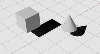
在 Isaac Sim 的示例中,打开 Isaac Examples > ROS > Teleport。此时,场景中会自动加载一个立方体和一个圆锥。
-
如果未打开 Action Graph 窗口,请通过菜单:Window > Visual Scripting > Action Graph
-
此时工作图(graph)应只包含两个节点:

-
On Playback Tick
-
ROS1 Teleport Service
-
-
要调用该服务,请在另一个终端中,加载 Isaac Sim 的 ROS1 工作区,然后运行示例客户端脚本:rosrun isaac_tutorials ros_service_client.py
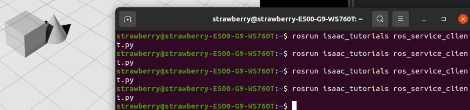
你会看到立方体和圆锥像中了瞬移咒一样,每次都会跳到随机的新位置。😉
Pose Teleport Service 消息定义
该服务使用一个自定义的 IsaacPose ROS Service 消息,定义文件位于:
/src/isaac_ros_messages/srv/IsaacPose.srv消息结构如下:
std_msgs/Header headerstring[] namesgeometry_msgs/Pose[] posesgeometry_msgs/Twist[] velocitiesgeometry_msgs/Vector3[] scales-
names:一个字符串数组,包含要传送对象的 prim 路径,必须与场景中的路径完全一致。
-
poses:一个
Pose数组,与names一一对应,指定每个对象的目标位置。 -
(可选)velocities 和 scales 可用于同时设置速度和缩放,但在本示例中未用到。
客户端示例脚本
下面是示例中运行的客户端脚本,位于:
/src/isaac_tutorials/scripts/ros_service_client.pyimport rospyimport numpy as npfrom isaac_ros_messages.srv import IsaacPose, IsaacPoseRequestfrom geometry_msgs.msg import Posedef teleport_client(msg): rospy.wait_for_service(\"teleport\") try: teleport = rospy.ServiceProxy(\"teleport\", IsaacPose) teleport(msg) except rospy.ServiceException as e: print(\"Service call failed: %s\" % e)# 随机生成立方体的新位置cube_pose = Pose()cube_pose.position.x = np.random.uniform(-2, 2)cube_pose.position.y = 0cube_pose.position.z = 0cube_pose.orientation.w = 1# 随机生成圆锥的新位置cone_pose = Pose()cone_pose.position.x = 0cone_pose.position.y = np.random.uniform(-2, 2)cone_pose.position.z = 0cone_pose.orientation.w = 1# 组装服务请求teleport_msg = IsaacPoseRequest()teleport_msg.names = [\"/World/Cube\", \"/World/Cone\"]teleport_msg.poses = [cone_pose, cube_pose]# 调用服务teleport_client(teleport_msg)2. ROS导航
学习目标
在本 ROS 示例中,我们将:
-
演示 Omniverse Isaac Sim 与 ROS Navigation 栈的集成。
-
使用地图生成器(Occupancy Map Generator)。
2.1 前提条件
-
安装 ROS Navigation 栈
在终端中运行:sudo apt-get install ros-$ROS_DISTRO-navigation这样就能获取所有核心的导航功能包了。
-
获取示例所需包
本教程依赖以下三个 ROS 包,它们位于你的工作空间下的src/navigation/目录中:-
carter_2dnav -
carter_description -
isaac_ros_navigation_goal
这些包分别包含:
-
启动文件(launch files)
-
导航参数配置
-
机器人模型文件
确保你已经完成了 ROS 和 ROS 2 的安装,且正确配置了 ROS 环境变量(例如
source /opt/ros/$ROS_DISTRO/setup.bash),并且src/navigation/已在你的ROS_PACKAGE_PATH中。 -
-
启用 ROS 桥接并启动 roscore
-
可选:如果你对 RTX 激光雷达(Lidar)传感器的工作原理、相关节点,或如何获取合成数据感兴趣,可阅读《RTX Lidar 传感器原理与使用指南》,深入了解它们在导航中的应用。
2.2 ROS导航设置
下面是该 ROS Navigation 栈所需的主要话题及其消息类型,对应图中的各个模块:
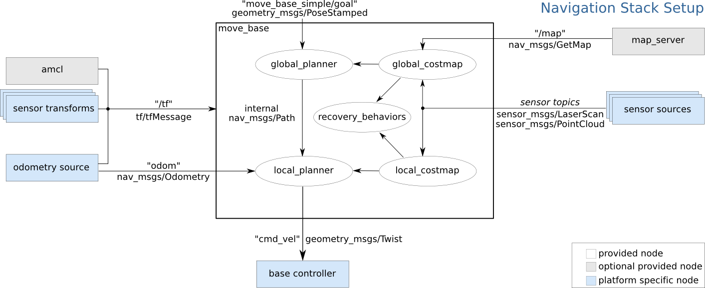
/tftf2_msgs/TFMessage/odomnav_msgs/Odometry/mapnav_msgs/OccupancyGrid/scansensor_msgs/LaserScan各模块如何利用这些话题
-
/map&map_server→global_costmap→global_planner
全局地图加载后,global_costmap将其转成代价地图,再由全局规划器计算从起点到目标的粗略路径。 -
/odom&/tf→ local_planner & local_costmap
局部代价地图不断融合里程计和雷达数据,为local_planner提供实时障碍物信息,生成可执行的局部路径。 -
/scan→ global_costmap & local_costmap
激光数据同时更新全局和局部代价地图,保证导航对新出现的障碍物能够“眼观六路、耳听八方”。 -
tf2_msgs/TFMessage
/tf话题上广播的坐标变换,让各节点能够把传感器数据、位姿、路径都正确地“放”到同一个世界坐标系下。
2.3 Carter_ROS Omnigraph 节点说明
在 Isaac Examples → ROS → Navigation 中加载仓库场景(warehouse scenario)。
Graph 说明
-
展开 Carter_ROS,右键点击 ActionGraph,选择 Open Graph。图中的控制部分就是经典的两轮小车graph,重点看ros部分:
-
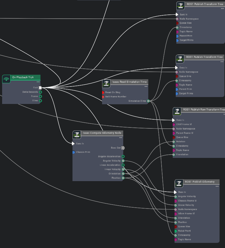
下列 ROS Omnigraph 节点负责驱动机器人导航:
Omnigraph 节点 功能说明 ros1_subscribe_twist订阅 /cmd_vel话题,将接收到的速度指令传给差速与关节控制器,控制机器人运动。isaac compute odometry node 它接收来自仿真环境或底层传感器(如 IMU、轮编码器)的原始运动数据,执行必要的计算(如积分、滤波、运动学解算),输出机器人当前的状态估计。 ros1_publish_odometry接收来自 Compute Odometry Node的完整状态信息(位置、姿态、线速度、角速度),将其封装成标准的 ROSnav_msgs/Odometry消息,并发布到指定的 ROS topic 上。ros1_publish_raw_transform_tree接收来自 Compute Odometry Node的位置和姿态信息,将其转换为 ROS 的坐标变换 (tf transform),并按照指定的父子坐标系关系持续发布到 ROStf树中。ros1_publish_transform_tree发布机器人基座坐标系(base_link)到底盘坐标系(chassis_link)的静态变换;由于目标 prim 设置为 Carter_ROS,会把整个 Carter 机器人从chassis_link开始的层级树都作为base_link的子树一起发布。ros1_publish_transform_tree_01发布底盘坐标系(chassis_link)到激光雷达坐标系(carter_lidar)的静态变换。 ros1_publish_laser_scan发布由 isaac_read_lidar_beams_node读取的 2D 激光扫描(LaserScan)数据。 -
同样在 Carter_ROS 下,右键点击 ROS_Cameras,选择 Open Graph。下列 ROS 相机相关 Omnigraph 节点负责图像与相机信息的发布:
这个好理解,就是有两个相机,然后每个相机都要进行渲染画面,然后分成三种类型和话题发布。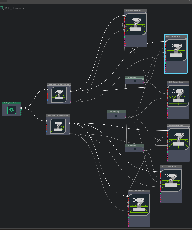
Omnigraph 节点 功能说明 ros1_create_camera_left_info自动生成并发布 /camera_info_left的CameraInfo,默认已启用enable_camera_left分支节点。ros1_create_camera_left_rgb自动生成并发布 /rgb_left的 RGB 图像,默认已启用enable_camera_left和enable_camera_left_rgb。ros1_create_camera_left_depth自动生成并发布 /depth_left的深度图(32FC1),需启用enable_camera_left和enable_camera_left_depth。ros1_create_camera_right_info自动生成并发布 /camera_info_right的CameraInfo,需启用enable_camera_right。ros1_create_camera_right_rgb自动生成并发布 /rgb_right的 RGB 图像,默认已启用enable_camera_right和enable_camera_right_rgb。ros1_create_camera_right_depth自动生成并发布 /depth_right的深度图(32FC1),需启用enable_camera_right和enable_camera_right_depth。 
- 为了让所有外部 ROS 节点使用仿真时间,还额外添加了一个 ROS_Clock Graph,包含一个
ros1_publish_clock节点,负责将仿真时间发布到/clock话题。
2.4 生成 Occupancy Map
使用占据地图生成器扩展(推荐)
要了解更多关于占据地图生成器扩展的信息,请点击此处。
-
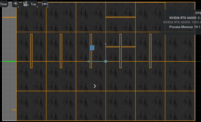
在 Isaac Examples → ROS → Navigation 中加载仓库场景(warehouse scenario)。
-
在视口左上角,点击 Camera,从下拉菜单中选择 Top(俯视图)。
-
进入 Isaac Utils → Occupancy Map。
-
在 Occupancy Map 扩展面板中:
-
将 Origin 设置为
X: 0.0, Y: 0.0, Z: 0.0。 -
将 Lower Bound 的
Z设置为0.1。 -
将 Upper Bound 的
Z设置为0.62。
提示:将上界
Z设为 0.62 米,是为了与 Carter 机器人上激光雷达距离地面的垂直高度保持一致。 -
-
在场景(Stage)中选中
warehouse_with_forklifts这个 prim。 -
返回 Occupancy Map 扩展面板,点击 BOUND SELECTION。此时,占据地图的边界将根据所选
warehouse_with_forkliftsprim 自动更新。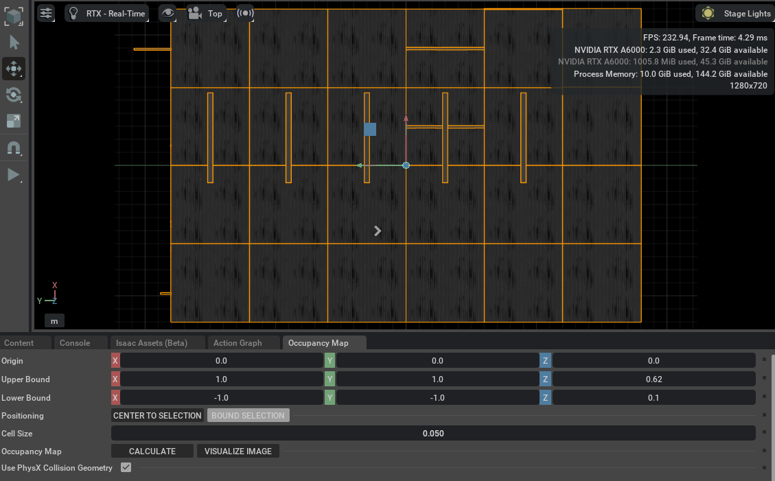
此时,面板中的地图参数就会类似于下图所示。
移除 Carter_ROS prim 并生成导航地图
-
移除 Carter_ROS prim
在场景(Stage)中,选中Carter_ROSprim,按 Delete 键将其移除。 -
计算并可视化占据图像
-
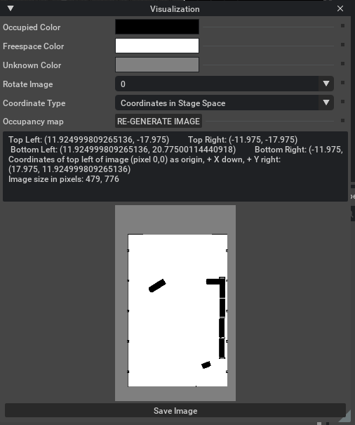
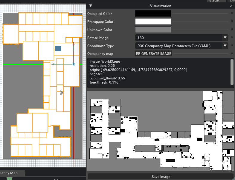
在 Occupancy Map 扩展面板中,依次点击 CALCULATE,然后点击 VISUALIZE IMAGE。
-
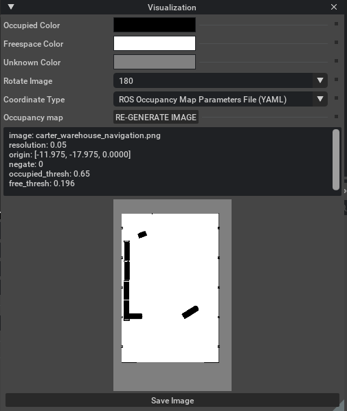
弹出可视化窗口后,设置:
-
Rotate Image:选择 180 degrees。
-
Coordinate Type:选择 ROS Occupancy Map Parameters File (YAML)。
-
-
点击 RE-GENERATE IMAGE,重新生成图像(因为 ROS 相机与 Isaac Sim 相机坐标系不同,需要翻转)。
-
-
导出 YAML 参数
-
在可视化面板下方,即刻会显示一段符合 ROS 格式的 Occupancy Map 参数(YAML 文本)。
-
复制全部文本内容。
image: carter_warehouse_navigation.pngresolution: 0.05origin: [-11.975, -17.975, 0.0000]negate: 0occupied_thresh: 0.65free_thresh: 0.196
-
-
创建并保存 YAML 文件
在你的carter_2dnavROS 包的map目录下(路径示例:/src/navigation/carter_2dnav/map/),新建一个名为carter_warehouse_navigation.yaml 的文件,将剪贴板中复制的 YAML 文本粘贴到该文件中并保存。 -
保存可视化图像:
回到 Omniverse Isaac Sim 可视化窗口,点击 Save Image。将文件命名为 carter_warehouse_navigation.png,将它保存在与carter_warehouse_navigation.yaml相同的目录中。
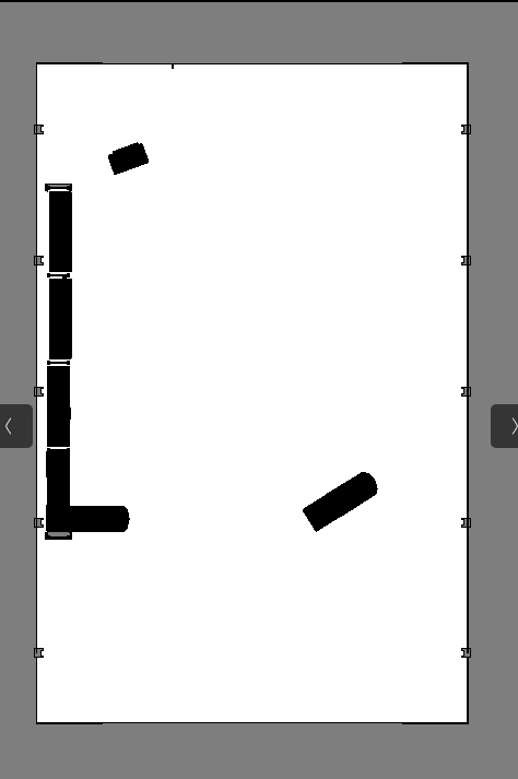 An occupancy map 现在就准备好了
2.5 运行 ROS Navigation
-
在 Isaac Examples → ROS → Navigation 中加载仓库场景(warehouse scenario)。
-
点击 Play 按钮,启动仿真。
-
打开一个新终端,运行以下 ROS 启动文件,开启导航流程:
这时 RViz 会自动打开,加载机器人的 URDF 模型、全局占据地图,以及覆盖其上的局部代价地图。roslaunch carter_2dnav carter_navigation.launch 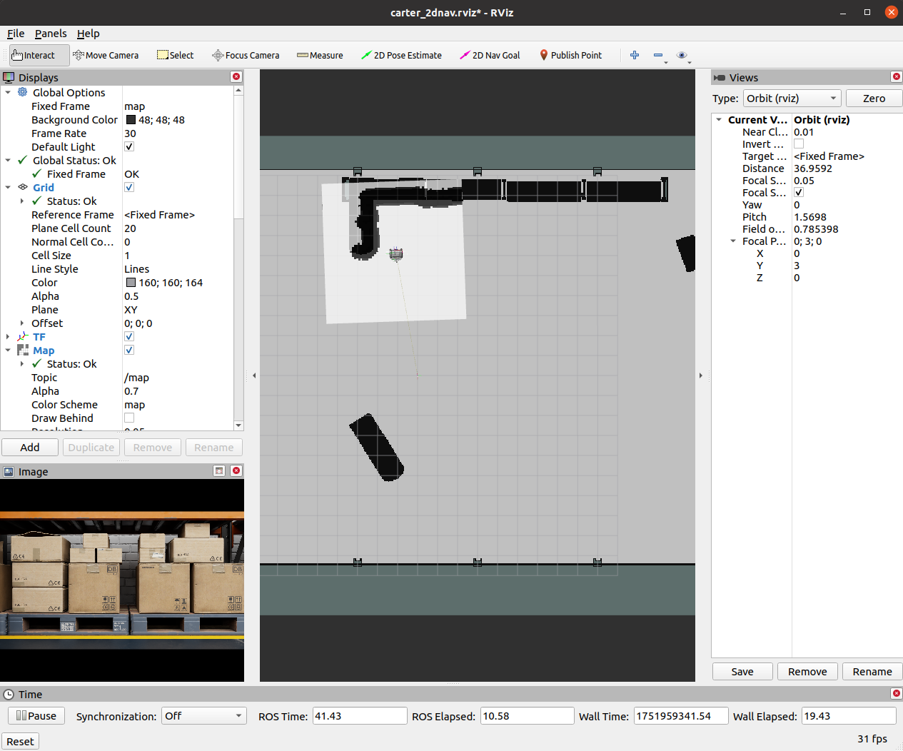
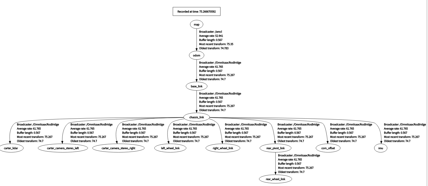
- 为验证所有坐标变换(TF)都正常广播,再打开一个新终端,运行:
rosrun rqt_tf_tree rqt_tf_tree弹出的 TF 树图应与下图大致相符。
-
由于
carter_navigation.launch中已定义机器人的初始位姿,启动时机器人会自动定位好;如有需要,也可在 RViz 中点击 2D Pose Estimate 按钮,手动重置位姿。 -
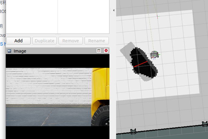
在 RViz 中,点击工具栏上的 2D Nav Goal,然后在地图上点击并拖拽至目标点。
ROS Navigation 栈会立即规划一条轨迹,机器人也会像开了自动驾驶模式一样,朝着目的地优雅行驶!
可以看到拖拽到损失很大的障碍物处是没法继续移动的。
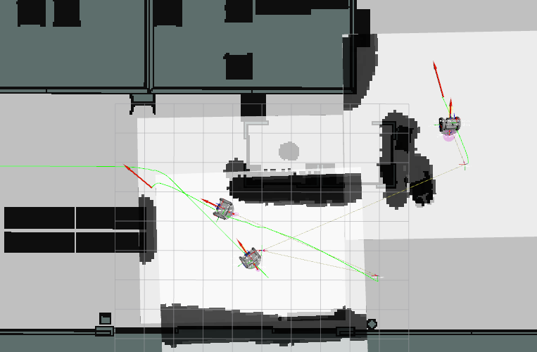
3. 多机器人ROS导航
3.1 建map
-
Create -> Isaac -> Environments -> Hospital.
-
Perspective--Top. 选中 Hospital prim and press F
-
Next, go to Isaac Utils -> Occupancy Map.
-
In the Occupancy Map extension, ensure the Origin is set to
X: 0.0, Y: 0.0, Z: 0.0. For the lower bound, setZ: 0.1. For the Upper Bound, setZ: 0.62. Keep in mind, the upper bound Z distance has been set to 0.62 meters to match the vertical distance of the Lidar onboard Carter with respect to the ground. -
Select the Hospital prim in the stage. In the Occupancy Map extension, click on
BOUND SELECTION. The bounds of the occupancy map should be updated to incorporate the selected Hospital prim. -
CALCULATEfollowed byVISUALIZE IMAGE. -
For Rotate Image, select 180 degrees and for Coordinate Type select
ROS Occupancy Map Parameters File (YAML). ClickRE-GENERATE IMAGE. Occupancy map parameters formatted to YAML will appear in the field below. Change the image name to your preference. Copy the full text. -
Create a YAML file for the occupancy map parameters called
carter_hospital_navigation.yamland place it in the map directory which is located in the samplecarter_2dnavROS package (carter_2dnav/map/carter_hospital_navigation.yaml). -
Insert the previously copied text in the
carter_hospital_navigation.yamlfile.
3.2 开始运行
-
Load scenario:
-
For the hospital environment, go to Isaac Examples -> ROS -> Multi Robot Navigation -> Hospital Scene.
-
For the Office scenario, go to Isaac Examples -> ROS -> Multi Robot Navigation -> Office Scene.
-
-
Click on
Playto begin simulation. -
In a new terminal, run the ROS launch file and set the env_name parameter to either hospital or office to begin Multiple Robot Navigation with the desired environment.
roslaunch carter_2dnav multiple_robot_carter_navigation.launch env_name:=hospital
To verify that all of the transforms are broadcasting, run the following command in a new terminal to visualize the ROS TF frame tree:
rosrun rqt_tf_tree rqt_tf_treeSince the positions of each robot is defined in multiple_robot_carter_navigation.launch, the robots should already be properly localized.
-
In RViz, 点击 Tool Properties -> 2D Nav Goal -> Topic, 设置 topic namespace to either
/carter1,/carter2or/carter3选择给哪一个导航 -
Next, click on the
2D Nav Goalbutton and then click and drag at the desired location point in the map. The ROS Navigation stack will now generate a trajectory and the specified robot will start moving towards its destination! Repeat this process for every other robot.